Địa điểm mua hàng
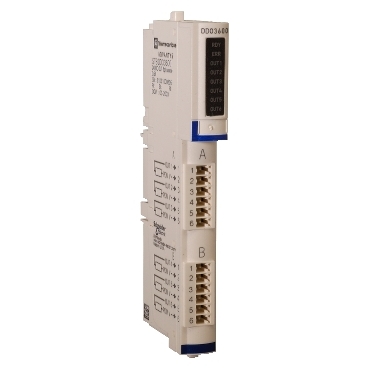
STBDDO3600K – standard digital output kit STB – 24 V DC – 6 O | Schneider Electric Global
Adaptable to network
Simple, open and flexible
Save time, money by simplifying maintenance, diagnostic task
Standard NIMs hot swapping
Power protection integrated fuse on PDM time lag 10A
Environmental performance of the product Learn more

Tùy chọn giao dịch

Tùy chọn thanh toán
Description
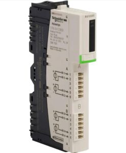
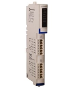
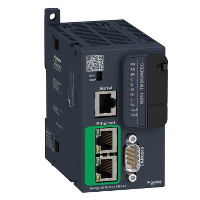
This product is part of the Modicon STB range, an offer of modular distributed I/O. This standard discrete output kit has 6 discrete outputs with solid state relay. It is a discrete output kit with a rated supply voltage of 24V DC and a current consumption of 90mA at 5V DC for logic bus. This product is compatible with most major fieldbus networks. It is an IP20 rated product. Its dimensions are 128.3mm (width) x 70mm (depth) x 13.9mm (height) and weighs 0.114kg. It is suitable for packaging, bottling, assembly, distribution, textile, printing and semiconductor machines applications. This product is certified by FM Class 1 Division 2, CE, UL and CSA. It meets EN/IEC 61131-2 type 3 standards. This kit is suitable for use with power distribution module STBPDT3100/3105 and I/O base STBXBA1000. The kit includes STBXBA1000 base, STBDDO3600 module, STBXTS2100, 6-terminal spring clamp connector and STBXTS1100, 6-terminal screw type connector. The Modicon LMC058 is the optimum solution for axis control and positioning, including automation functions. It forms a part of flexible machine control approach, a key component of MachineStruxure.
Specifications
| Range of product | Modicon STB distributed I/O solution |
|---|---|
| Product or component type | Standard digital output kit |
| kit composition | STBXBA1000 base STBDDO3600 module STBXTS2100, 6-terminal spring clamp connector STBXTS1100, 6-terminal screw type connector |
| Discrete output number | 6 |
| discrete output type | Solid state |
| discrete output voltage | 24 V |
| discrete output voltage type | DC |
| Discrete output current | 500 mA |
|---|---|
| discrete output logic | Positive or negative |
| Output voltage | 19.2…30 V DC |
| Absolute maximum voltage | 56 V 1.3 ms |
| Response time | 715 µs off-to-on 955 µs on-to-off |
| Cold swapping | Yes |
| hot swapping | Yes for standard NIMs |
| fallback | State 0 basic NIMs User configurable standard NIMs |
| Protection type | Power protection integrated fuse on PDM time lag 10 A Reverse polarity protection Short-circuit protection Thermal overload protection |
| Insulation between channels and logic bus | 1500 V for 1 minute |
| Maximum leakage current | 0.4 mA at state 0 30 V |
| Surge current | 5 A 0.5 ms |
| Maximum load capacitance | 50 µF |
| Maximum load inductance | 500 mH at 4 Hz |
| Minimum load | 0.5 mA |
| Reset | Manual reset COM fault |
| Product compatibility | Power distribution module STBPDT3100/3105 I/O base STBXBA1000 |
| [Us] rated supply voltage | 24 V DC |
| Supply | Power distribution module |
| Current consumption | 90 mA at 5 V DC for logic bus |
| Marking | CE |
| Overvoltage category | II |
| Status LED | 1 LED (green) module status (RDY) 1 LED per channel (green) channel status (OUT1 to OUT6) 1 LED (red) module error (ERR) |
| Height | 13.9 mm |
| depth | 70 mm |
| Width | 128.3 mm |
| Net weight | 0.114 kg |
| Standards | EN/IEC 61131-2 |
|---|---|
| product certifications | CSA UL FM Class 1 Division 2 |
| Pollution degree | 2 conforming to IEC 60664-1 |
| Operating altitude | <= 2000 m |
| IP degree of protection | IP20 conforming to EN 61131-2 class 1 |
| Ambient air temperature for operation | 0…60 °C (without derating) |
| Ambient air temperature for operation | 32…140 °F without derating |
| Ambient air temperature for storage | -40…85 °C without derating |
| Ambient air temperature for storage | -40…185 °F without derating |
| Relative humidity | 95 % at 60 °C without condensation |
| Vibration resistance | 3 gn at 58…150 Hz on 35 x 7.5 mm symmetrical DIN rail 5 gn at 58…150 Hz on 35 x 15 mm symmetrical DIN rail +/-0.35 mm at 10…58 Hz |
| Shock resistance | 30 gn for 11 ms conforming to IEC 88 reference 2-27 |
| Unit Type of Package 1 | PCE |
|---|---|
| Number of Units in Package 1 | 1 |
| Package 1 Height | 2.7 cm |
| Package 1 Width | 8.0 cm |
| Package 1 Length | 13.0 cm |
| Package 1 Weight | 136.0 g |
| Unit Type of Package 2 | S02 |
| Number of Units in Package 2 | 28 |
| Package 2 Height | 40 cm |
| Package 2 Width | 30 cm |
| Package 2 Length | 15 cm |
| Package 2 Weight | 4.425 kg |
| Warranty | 18 months |
|---|
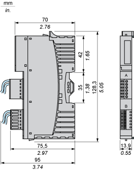
Dimensions Drawings
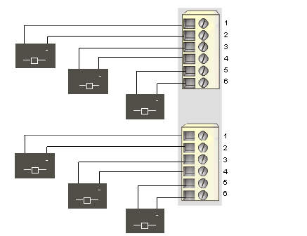
Connections and Schema
6 two-wire actuators
|
Pin |
Top Connector |
Bottom Connector |
|---|---|---|
|
1 |
output to actuator 1 |
output to actuator 4 |
|
2 |
field power return |
field power return |
|
3 |
output to actuator 2 |
output to actuator 5 |
|
4 |
field power return |
field power return |
|
5 |
output to actuator 3 |
output to actuator 6 |
|
6 |
field power return |
field power return |

