Địa điểm mua hàng
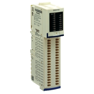
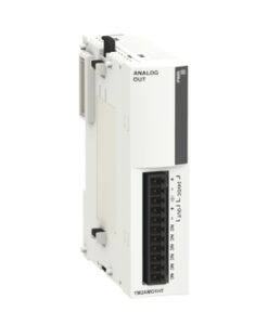
STBDDO3705 – basic digital output module STB – 24 V DC – 16 O | Schneider Electric Global
Integrated power protection fuse on PDM time lag 5A
IP20 degree of protection
CE approved
FM, UL and CSA certified
Wide range of operating temperature from 0°C to 60°C
Environmental performance of the product Learn more

Tùy chọn giao dịch

Tùy chọn thanh toán
Description
This output module is part of the Modicon STB range, an offer of IP20 modular distributed I/Os on multiple networks and fieldbus. This basic digital output module offers 16 outputs with positive discrete output logic. It offers discrete output voltage of 24V DC with solid state discrete output. There is an insulation between channels and logic bus at 1500V for 1 minute. It is an IP20 rated product. Its dimensions are 128.3mm (width) x 70mm (depth) x 13.9mm (height). It weighs 0.086kg. It is suitable for packaging, bottling, assembly, distribution, textile, printing and semiconductor machines. This product is certified by CE, FM Class 1 Division 2, CSA and UL. It meets EN/IEC 61131-2 standard. It is compatible with I/O base STBXBA3000 and power distribution module STBPDT3100/3105. Advantys distributed I/O solutions are simple, open and flexible, meeting needs in every stage of the product life cycle. For distributed connection to sensors and actuators from a PLC with prefabricated cables.
Specifications
| Range of product | Modicon STB distributed I/O solution |
|---|---|
| Product or component type | Basic digital output module |
| Discrete output number | 16 |
| discrete output type | Solid state |
| discrete output voltage | 24 V |
| discrete output voltage type | DC |
| Discrete output current | 500 mA |
|---|---|
| discrete output logic | Positive |
| Output voltage | 19.2…30 V DC |
| Absolute maximum voltage | 35 V 1.3 ms |
| Response time | 2 ms off-to-on 2 ms on-to-off |
| Cold swapping | Yes |
| hot swapping | No for basic NIMs |
| Protection type | Power protection integrated fuse on PDM time lag 5 A Reverse polarity protection Short-circuit protection Thermal overload protection |
| Insulation between channels and logic bus | 1500 V for 1 minute |
| Maximum leakage current | 0.4 mA at state 0 30 V |
| Maximum load capacitance | 10 µF |
| Maximum load inductance | 1000 mH at 4 Hz |
| Reset | Manual reset COM fault |
| Product compatibility | Power distribution module STBPDT3100/3105 I/O base STBXBA3000 |
| [Us] rated supply voltage | 24 V DC |
| Supply | Power distribution module |
| Current consumption | 135 mA at 5 V DC for logic bus |
| Marking | CE |
| Overvoltage category | II |
| Status LED | 1 LED (green) module status (RDY) 1 LED per channel (green) channel status (OUT1 to OUT16) |
| Height | 13.9 mm |
| depth | 70 mm |
| Width | 128.3 mm |
| Net weight | 0.086 kg |
| Standards | EN/IEC 61131-2 |
|---|---|
| product certifications | UL CSA FM Class 1 Division 2 |
| Pollution degree | 2 conforming to IEC 60664-1 |
| Operating altitude | <= 2000 m |
| IP degree of protection | IP20 conforming to EN 61131-2 class 1 |
| Ambient air temperature for operation | 0…60 °C (without derating) |
| Ambient air temperature for operation | 32…140 °F without derating |
| Ambient air temperature for storage | -40…85 °C without derating |
| Ambient air temperature for storage | -40…185 °F without derating |
| Relative humidity | 95 % at 60 °C without condensation |
| Vibration resistance | 3 gn at 58…150 Hz on 35 x 7.5 mm symmetrical DIN rail 5 gn at 58…150 Hz on 35 x 15 mm symmetrical DIN rail +/-0.35 mm at 10…58 Hz |
| Shock resistance | 30 gn for 11 ms conforming to IEC 88 reference 2-27 |
| Unit Type of Package 1 | PCE |
|---|---|
| Number of Units in Package 1 | 1 |
| Package 1 Height | 3.05 cm |
| Package 1 Width | 6.6 cm |
| Package 1 Length | 12.95 cm |
| Package 1 Weight | 100 g |
| Unit Type of Package 2 | S02 |
| Number of Units in Package 2 | 48 |
| Package 2 Height | 15 cm |
| Package 2 Width | 30 cm |
| Package 2 Length | 40 cm |
| Package 2 Weight | 5.322 kg |
| Unit Type of Package 3 | P06 |
| Number of Units in Package 3 | 768 |
| Package 3 Height | 75.0 cm |
| Package 3 Width | 60.0 cm |
| Package 3 Length | 80.0 cm |
| Package 3 Weight | 95.1 kg |
| Warranty | 18 months |
|---|
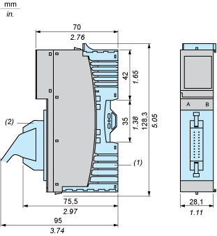
Dimensions Drawings
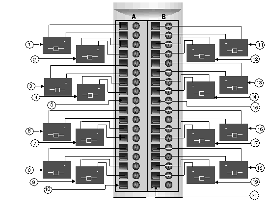
16 two-wire actuators
|
# |
Group 1 |
# |
Group 2 |
|---|---|---|---|
|
1 |
Channel 1, Connector A, Actuator |
11 |
Channel 1, Connector B, Actuator |
|
2 |
Channel 2, Connector A, Actuator |
12 |
Channel 2, Connector B, Actuator |
|
3 |
Channel 3, Connector A, Actuator |
13 |
Channel 3, Connector B, Actuator |
|
4 |
Channel 4, Connector A, Actuator |
14 |
Channel 4, Connector B, Actuator |
|
5 |
Pin 9, Connector A (not used) |
15 |
Pin 9, Connector B (not used) |
|
6 |
Channel 5, Connector A, Actuator |
16 |
Channel 5, Connector B, Actuator |
|
7 |
Channel 6, Connector A, Actuator |
17 |
Channel 6, Connector B, Actuator |
|
8 |
Channel 7, Connector A, Actuator |
18 |
Channel 7, Connector B, Actuator |
|
9 |
Channel 8, Connector A, Actuator |
19 |
Channel 8, Connector B, Actuator |
|
10 |
Pin 18, Connector A (not used) |
20 |
Pin 18, Connector B (not used) |

