Địa điểm mua hàng
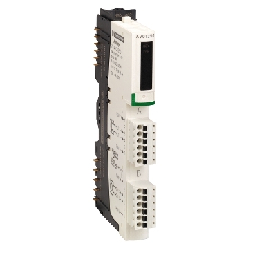
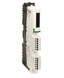
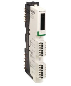
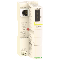
STBAVO1250K – standard analog output kit STB – +/- 10 V – 2 O – 12 bits | Schneider Electric Global
Easy to connect
2 outputs
Power supply +/- 10 V
Environmental performance of the product Learn more

Tùy chọn giao dịch

Tùy chọn thanh toán
Description
This output kit is part of the Modicon STB range, an offer of modular distributed I/O. This standard analog output kit has 2 analog outputs with 11bit + sign and 12bit output resolution. This analog output kit has a rated supply voltage of 24V DC and a current consumption of 45mA at 5V DC for logic bus. This product is compatible with most major fieldbus networks. Configuration can be done via Advantys STB configuration software. This product is IP20 rated. Its dimensions are 128.3mm (width) x 70mm (depth) x 13.9mm (height). It weighs 0.116kg. It is suitable for packaging, bottling, assembly, distribution, textile, printing and semiconductor machines applications. This product is certified by FM Class 1 Division 2, CE, UL and CSA. This kit is suitable for use with mounting base STBXBA1000 and power distribution module STBPDT3100/3105. The kit includes STBXBA1000 base, STBAVI1270 module, STBXTS1100 6-terminal screw type connector, and STBXTS2100 6-terminal spring clamp connector. The Modicon STB distributed I/O solution is an open, modular input/output system that makes it possible to design automation islands managed by a primary controller via a bus or communication network.
Specifications
| Range of product | Modicon STB distributed I/O solution |
|---|---|
| Product or component type | Standard analog output kit |
| kit composition | STBXTS1100, 6-terminal screw type connector STBXTS2100, 6-terminal spring clamp connector STBAVO1250 module STBXBA1000 base |
| Analogue output type | Voltage: +/- 10 V Voltage: 0…10 V |
| Analogue output number | 2 |
| Analogue output resolution | 11 bits + sign, +/- 10 V 12 bits, 0…10 V |
| Analogue output current | 0.005 A |
|---|---|
| Response time | 3 ms |
| Cold swapping | Yes |
| hot swapping | Yes for standard NIMs |
| fallback | State 0 basic NIMs User configurable standard NIMs |
| Data format | EN 61131-2 IEC 61131-2 |
| Update time | 25 ms |
| Protection type | Short-circuit protection |
| Integral linearity | +/- 0.1 %FS |
| Differential linearity | Monotonic |
| Absolute accuracy error | +/- 0.5 % of full scale at 25 °C |
| Temperature drift | +/-0.01 %/°C |
| Insulation between channels and logic bus | 1500 V for 1 minute |
| Insulation between channels and actuator bus | 30 V |
| Addressing requirement | 2 non-adjacent input bytes (module and channel status diagnostics) 2 output words |
| Product compatibility | Power distribution module STBPDT3100/3105 Mounting base STBXBA1000 |
| [Us] rated supply voltage | 24 V DC |
| Supply | Power distribution module |
| Current consumption | 45 mA at 5 V DC for logic bus |
| Marking | CE |
| Overvoltage category | II |
| Status LED | 1 LED (green) module status (RDY) 1 LED (red) module error (ERR) |
| depth | 70 mm |
| Height | 13.9 mm |
| Width | 128.3 mm |
| Net weight | 0.116 kg |
| product certifications | UL CSA FM Class 1 Division 2 |
|---|---|
| Pollution degree | 2 conforming to IEC 60664-1 |
| Operating altitude | <= 2000 m |
| IP degree of protection | IP20 conforming to EN 61131-2 class 1 |
| Ambient air temperature for operation | 0…60 °C (without) |
| Ambient air temperature for operation | 32…140 °F without |
| Ambient air temperature for storage | -40…85 °C without |
| Ambient air temperature for storage | -40…185 °F without |
| Relative humidity | 95 % at 60 °C without condensation |
| Vibration resistance | 3 gn at 58…150 Hz on 35 x 7.5 mm symmetrical DIN rail 5 gn at 58…150 Hz on 35 x 15 mm symmetrical DIN rail +/-0.35 mm at 10…58 Hz |
| Shock resistance | 30 gn for 11 ms conforming to IEC 88 reference 2-27 |
| Unit Type of Package 1 | PCE |
|---|---|
| Number of Units in Package 1 | 1 |
| Package 1 Height | 2.5 cm |
| Package 1 Width | 8.0 cm |
| Package 1 Length | 13.0 cm |
| Package 1 Weight | 137.0 g |
| Unit Type of Package 2 | S02 |
| Number of Units in Package 2 | 28 |
| Package 2 Height | 15.0 cm |
| Package 2 Width | 30.0 cm |
| Package 2 Length | 40.0 cm |
| Package 2 Weight | 4.262 kg |
| Unit Type of Package 3 | PAL |
| Number of Units in Package 3 | 448 |
| Package 3 Height | 60.0 cm |
| Package 3 Width | 80.0 cm |
| Package 3 Length | 448.0 cm |
| Package 3 Weight | 61.376 kg |
| Warranty | 18 months |
|---|
Dimensions Drawings
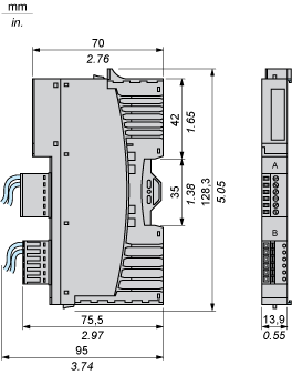
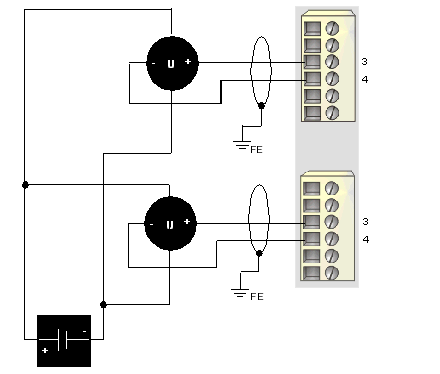
Connections and Schema
2 isolated analog actuators, external 24 VDC power supply
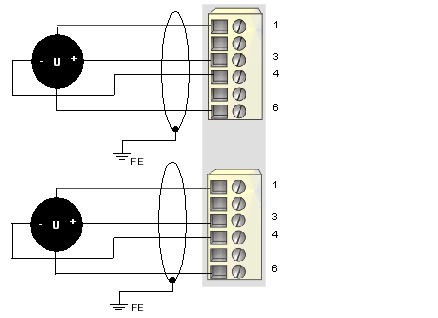
2 non-isolated analog actuators, 24 VDC supplied by the PDM
|
Pin |
Top Connections |
Bottom Connections |
|---|---|---|
|
1 |
+24 VDC from the island’s field power bus for field device accessories |
+24 VDC from the island’s field power bus for field device accessories |
|
2 |
no connection |
no connection |
|
3 |
output to actuator 1 |
output to actuator 2 |
|
4 |
output channel return |
output channel return |
|
5 |
no connection |
no connection |
|
6 |
field power return (to the module) |
field power return (to the module) |

